Source Synchronous Input Timing
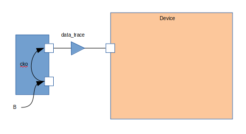
A source synchronous input is an interface in which the data is co-incident with a clock. In addition, there is a known relationship between the clock and the data. The diagram below illustrates the timing elements involved:
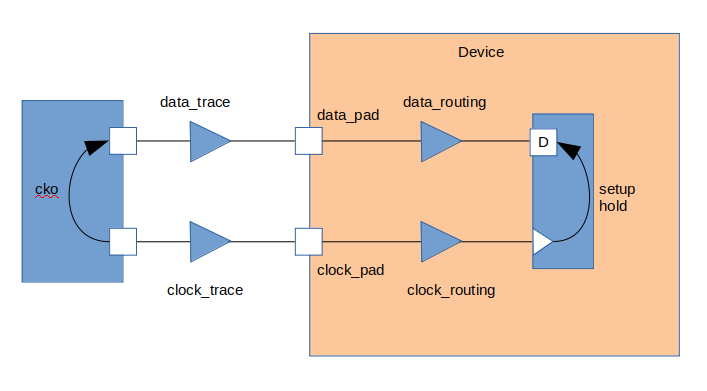
These can be divided into three major groups:
- Source Device Variables
- Trace Delays
- Device Delays
Waveform
The timing diagram below shows the setup and hold edges.

Data is launched from the rising edge of the launch clock. Data is captured on the risinge edge of the capture clock.
This means the setup check is from edge 1 to edge c. Data must be stable before edge C to pass the setup check at the capture flop.
The hold check is from edge 1 to edge a. Data must be held stable after edge A to pass the hold check at the capture flop.
Source Device Variables
Source device variables refer to constraints imposed on the input path by the device sending data. In a source synchronous interface the variables are:
- clock period
- clock to out (cko)
Clock Period
Setup checks are dependent on the frequency of the clock and will use the clock period variable. Hold checks are frequency independent, and will not use the clock period variable.
Clock to Out
The clock to out variable defines the relationship between the launching edge of the clock and the data. There will be maximum and minimum values.
The maximum is the time from the launching clock to the latest data will be valid. The minimum is the time from the launching clock to the earliest data will be invalid.
The difference between the two numbers defines the region in which data is unstable.
set t_cko_max 2.8
set t_cko_min 1.2
Trace delays
Trace delays represent the latency of signals from one device to another. They are also known as board delays or flight times.
Each trace will have a maximum and minimum delay. If there is a bus, then a maximum and minimum delay over the entire bus is typically calculated.
There will be delays for both data and clock.
set t_data_trace_max 1.2
set t_data_trace_min 0.4

set t_clock_trace_max 1.2
set t_clock_trace_min 0.4
Device Delays
Device delays represent the delays and constraints inside the device we are timing. They can be broken out into three distinct types:
- Pad Delays
- Routing Delays
- Setup and Hold Constraints
Pad Delays
Pad delays are the delays through the input pad. This was broken out seperately to illustrate different elements within the device.
Both the clock and data will have a maximum and minimum time through the pad.
set t_data_pad_max 1.2
set t_data_pad_min 0.4

set t_clock_pad_max 1.2
set t_clock_pad_min 0.4
Routing Delays
Routing delays are the delays each signal takes from the pad to the destination. For the data path, it includes any combinatorial logic and buffers to the D input of a capturing flop. For the clock path, it includes routing through the clock tree, any clock managers (DLLs, PLLs, etc…) to the clock input of the capturing flop.
set t_data_routing_max 1.2
set t_data_routing_min 0.4

set t_clock_routing_max 1.2
set t_clock_routing_min 0.4
Setup and Hold Constraints
The setup and hold constraints on the capturing flop represent the minimum times data must be stable on either side of the capturing clock edge. Setup defines the required stable time before the clock edge. Hold defines the required stable time after the clock edge.
set t_setup 0.5
set t_hold 0.5
Derive Hold Equation
For a hold check, the data must be held stable for some time after the clock transitions. To derive the hold equation, we need to check the worst case timing arcs. This requires using the least (fastest) data delay against the most (slowest) clock delay.
The equation is an inequality and we can re-arrange the equation:
We can see from this equation that if the data delay helps a hold check while clock delay and a positive hold requirements hurts.
Expanding the data and clock path yields:
This equation tells us if the is enough slack in the hold timing check.
A negative slack indicates the data path is not long enough to meet the hold requirement on the capturing flop. To fix this, either increase the delay in the data path and/or decrease the delay in the clock path.
Derive Setup Equation
For a setup check the data must be stable for some time before the clock transistions. To derive the setup equation, we need to check the worst case timing arcs. This requires using the most (slowest) data delay against the least (fastest) clock delay.
The equation is an inequality and we can re-arrange it to produce a slack equation:
We can see from this equation that clock delay helps a setup check while data delay and a positive setup requirement hurts.
Exanding the data and clock paths yields:
This equation tells us if there is enough slack in the setup timing check.
Writing Timing Constraints
The previous sections described the timing arcs and derived the equations. Now we need to write timing contraints to ensure the interface will be timed correctly. Writing the constraints involves the following steps:
- Create the receive clock
- Apply delays to input data path
It is important to write the constraints to match reality. The following will step through every command and explain why it is used.
Create Receive Clock
We will use the create_clock command to create the receive clock.
create_clock -period $clock_period -name $clock_pin [get_pins $clock_pin]
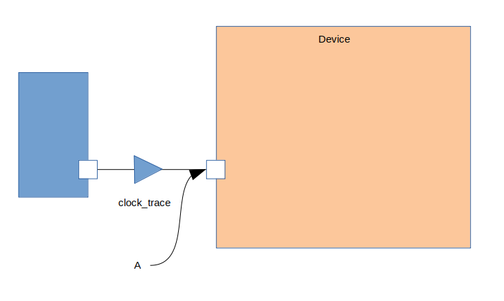
When the command is issued, the clock is placed on the input pin, point A in the diagram below:
However, we need to move the clock to point B in the diagram below:
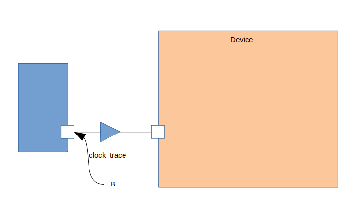
We move the clock to the output of the transmitting device using the set_clock_latency command:
set_clock_latency -source -max $t_clock_trace_max [get_clocks $clock_pin]
set_clock_latency -source -min $t_clock_trace_min [get_clocks $clock_pin]
The -max sets the maximum trace delay on the clock, while the -min will set the minimum trace delay on the clock. the -source indicates the delay on the clock is before the point the clock is defined.
Apply Delays to Data Path
We need to model the external world for the timing en By adding the just the trace delay, we will be placing the data at point A in the diagram below:
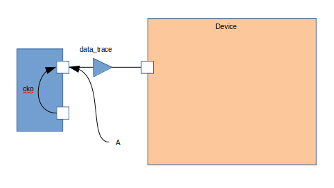
However, principle CLK-001 states for valid timing we must be able to trace back to the same clock point. We need to move the launching to point B in the diagram below:
We do this by adding the clock to out to the trace delay: The data path and clock path now originate from the same point so the timing analysis will be valid.
We will use the set_input_delay command to add the clock to out and data trace delay to the data pins. This command will also bind the clock to the data pins.
set_input_delay -clock [get_clocks $clock_pin] -max -source_latency_included [expr $t_cko_max + $t_data_trace_max] [get_pins $data_pins]
set_input_delay -clock [get_clocks $clock_pin] -min -source_latency_included [expr $t_cko_min + $t_data_trace_max] [get_pins $data_pins]
The -clock argument tells the timing tool the delays are relative to the clock specified. The -source_latency_included argument tells the timing tool we have added source latency to the clock path using the set_clock_latency command.
Validating Timing Report
It is crucial to validate the timing report generated by the STA tool. Various elements must be checked to ensure they match what we expect. This includes:
- launch clock edge
- capture clock edge
- input delay values
- clock pessimism recovery
- clock uncertainty
- data path cells
- clock path cells
- slack
Setup Report
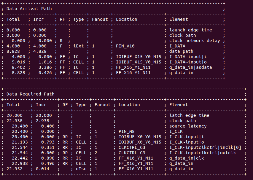
Below is an example setup report for this interface:
To validate this report against the constraints, we will be performing the following steps:
- Validate Clock Edges
- Validate Clock Source Latency
- Validate Input Delay
Validate Clock Edges
First thing we do is validate the timing edges:
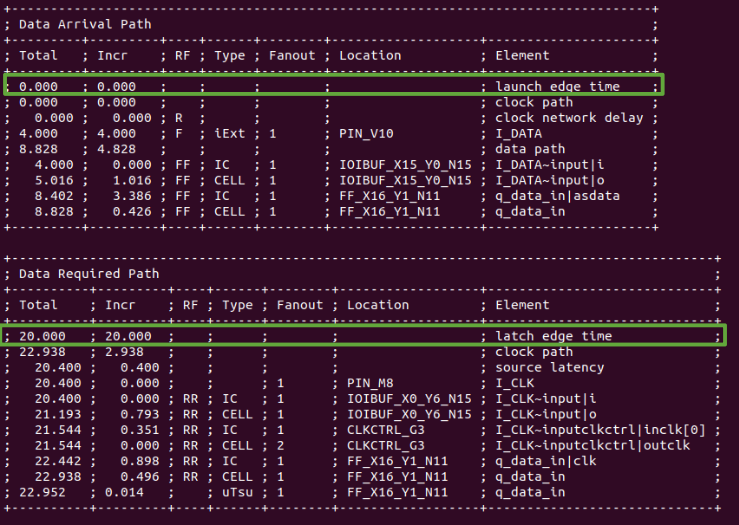
Refering to the waveform at the beginning, we expect the capture edge to be one clock cycle, 20 ns, from the launching edge. In the report, we see the launch edge is at 0.000 ns and the capture edge is at 20.000 ns. This validates we are using the correct edges.
Validate Clock Source Latency
Next we check the clock source latency is included:
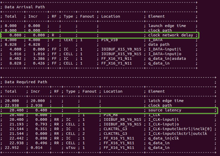
We check there is no clock latency reported in the data path. In this report, the clock_network_delay is set to 0.000 ns.
We check the source latency we defined is included in the clock path. In our case, t_clock_trace_min is defined as 0.400 ns. This matches the source latency value.
We also check the Element is the clock pin we expect. In this report, the clock path starts at the pin I_CLK
Everything is as we expected. This validates we have created the clock and the source clock latency has been applied correctly.
Validate Input Delay
Next we check the input delay in included:
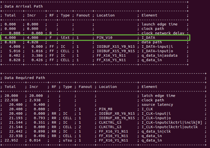
We check trhe input delay value is included and the correct value. In this report, iExt is the input delay value and is 4.000 ns. This matchtes the data latency where t_cko_max, 2.8 ns, plus t_data_trace_max, 1.2 ns, is equal to 4.000 ns.
We also check the Element is the data pin we expect. In this report, the data path starts at pin I_DATA.
Everything is as we expected. This validates the input delay is the correct value and has been applied to the correct pin.